Top Frog Lures for Bass Fishing in 2024: Best Picks & Laminator Comparison
Best obd2 Scanner- Best all in one printer
- Best printer scanner
- Best police scanner app
- Best scanner
- Best document scanner
- Best home printer scanner
- Best scanner app
What is the best color frog for bass fishing? Frog Lures for Bass Fishing 2021

RUNCL Fishing Baits Tackle

TROUTBOY Frog Fishing Lure

Croch Hollow Body Frog Lure…
What is the best color frog for bass fishing? Frog Lures for Bass Fishing 2021 Quick Navigation
Hide Content
- 1. RUNCL Fishing Baits Tackle
- 2. TROUTBOY Frog Fishing Lure
- 3. Croch Hollow Body Frog Lure Weedless Topwater Kit (18 PCS)
- 4. TECKEL Sprinker Topwater Frog
- 5. Lunkerhunt Lunker Frog Series 2.5-inch Green Tea Style Fishing Lure
- 6. Spro Bronzeye Frog 65 Bait-Pack of 1
- 7. Livetarget Hollow Body Frog
- 8. Supertrip Topwater Frog Crankbait Tackle Crank Bait Bass Soft Swimbait Lures Crankbaits Baits Hard Bait Fishing Lures (Multicolors)
What is the best color frog for bass fishing? Frog Lures for Bass Fishing 2021
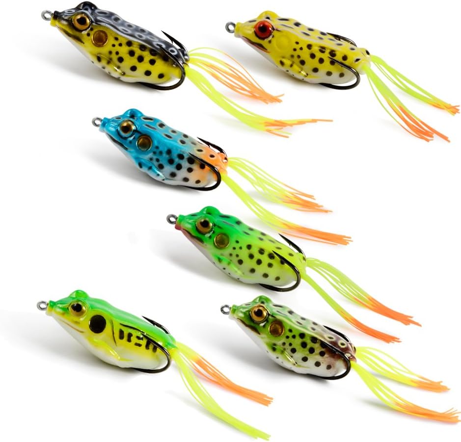
Frog lures are among the most effective tools of fishing. The best thing with these lures is that they can mimic the movements of a real frog. Their color is also similar to that of a real frog which makes them easier to attract fish. However, there are so many models of frog lures which makes it hard for anglers to determine the best. You also need to know how to use them. If you have been searching for the best topwater frog lures, we’ve got you covered. This article will reveal the best four frog lures you should consider today. We shall also cover some of the factors you are supposed to consider when buying these baits. If you have never used them before, you will learn some useful tips on how they work. Are you ready to learn? Check out the article.
Topwater Frog Fishing Tips
- Skimming across weeds – This method is one of the most common techniques and also the most challenging. It is very easy for the fish to miss the bait. The bass normally blows up the frog when you move it across the matted vegetation using a steady twitch of the rod. For you to do this successfully, skim the bait over the mat using a solid hook set and allow it to settle in the openings of the mat.
- Gear – The frog rod should be 7’3 or 7’6 and should have a good backbone. It should also have a limber tip to enable you to throw the bait further. You can also pair it with a baitcast reel. You only need to ensures that it has a heavy braided line.
- The frog – There are different frogs baits in the market. These frogs should have life-like features and the hook should be well set to catch the bass when it strikes.
- Location – The best place to use frog baits is in lily pads which is usually the natural habitat for frogs. After casting it in the lily pads, you should keep the rod tip up in such a way that the nose of the frog moves more efficiently over the lily pads.
After this, move the rod in a zigzag motion to enable the frog to walk over the water and lily pads in a classic motion. You should give it sometime before setting the hook once the bass strikes. This enables the fish to turn back with the bait in its mouth. Ensure that the hook is properly connected.
- Switch baits – Even if they have stopped blowing the buzz bait, it does not mean that the topwater bite is over. It is good to keep changing the bait. You can use a popper in the morning, frog or walking bait during the day.
- Keep trying – Many anglers find topwater fishing to be a bit challenging. Do not give up even if you will miss some fish. Try to be keen when timing and ensure that you are using the correct rod.
How to Use a Top Water Frog
This one is a very challenging task and not everyone can master this art. If you want to be successful in this, the most important thing is to know the angle you should place the topwater frog and how to connect it to the fish rod. You also need to know how to cast the frog on the water and how to throw them. For this technique to work, you need to ensure that the frog is appropriately connected to the fishing rod.
After you have connected it successfully, you can now deep them in the middle of the vegetation and start pulling it slowly it from the top. This technique helps in moving the frog to give it a realistic look.
Factors to Consider When Buying a Topwater Frog
- Size – Frog baits come in different sizes and shapes. There are those which works well in thick vegetation while others show some resistance. Whichever the case, ensure that the frog bait you choose will provide a lifelike impression.
- Colour – This is another important thing you must consider. Choose a color which resembles a real frog. The frog lure should have true like colors which can attract the fish.
Types of Frog Bait
Frog baits are designed using different materials. They also come in different designs which enables them to attract big fish. Some of the designs are as follows;
- Hollow Body Frog – This one has a hollow and a flexible body. It also features a double hook that is designed in an upturned manner. The body is very soft and collapses easily to catch the fish. It is mainly used in areas with thick grass of mats and a surface with a lot of vegetation.
- Propping Frog – These are available in a soft and hard-bodied frog. The most outstanding feature of this frog bait is that it splits water when it is placed on it. The propping movements give it a realistic look and this enables it to attract more fish. It is ideal for use in open water.
- Hard Plastic Frog – These frogs have a hard plastic body and contain an exposed hook. They have a color pattern and shape which gives them a realistic look. You can use the rod to create zigzag back and fro movements. This makes it ideal for open water which does not have a lot of vegetation.
- Soft Plastic Frog – these look like the hollowed body frogs but instead of floating on water, they sink. They kick and swim in water just like real frogs. When you move the rod, the frog swims across the surface but it sinks when you slow down. It is suitable for areas which have a lot of moss.
Why Should You Use a Frog Bait?
There are many advantages of using frog bait. Here are some of the benefits:
- They mimic the movement of real frogs which are found in water. This enables them to attract fish which feed on these frogs.
- Apart from floating on water, these frog baits are also able to sink depending on how you move the rod. This one enables the bait to be useful in different water bodies ranging from deep to narrow.
- They come in different colors and sizes which gives them a realistic appearance. The hooks are also strong and do not release the fish easily.
- They are versatile which means they can be used in open water surface or thick surface vegetation.
Best Topwater Frog Lures on the Market
1
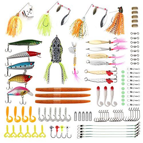
RUNCL Fishing Baits Tackle
This one has a lifelike design and is made in such a way that it imitates the natural swimming movements of a fish. The design enables anglers to catch bigger fish. The best thing is that it is very friendly to the environment since it is made of TCR which is a biodegradable material. This enables you to fish safely without any effect on the environment.
The material is soft and flexible which enables it to attract the fish. Another thing is that it features different lures such as metal spinning lures, spinnerbaits, worms, and crankbaits which makes it ideal for all fishing groups. Additionally, it comes with different hook sizes, weighted sinkers, and colored jig heads.
This enables you to choose the best lure for your preferred catch. If you are searching for the best set that you can use to catch any fish, this one might be what you are searching for. It measures 8.46 X4.33 X 1.77 Inches. To make your work easier, the set includes a doubled layer box which is very convenient for carrying.2
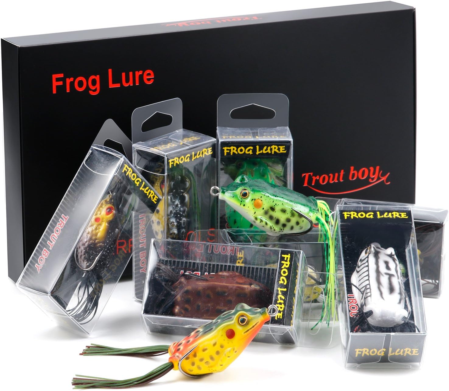
TROUTBOY Frog Fishing Lure
The TROUTBOY Frog Fishing Lure is another amazing product on the market. It has a soft and hollow body design which enables the frog lures to work smoothly without sinking. This also increases the Hook-up percentage. Apart from this, it has a life-like design with a high-resolution body detail.
It also imitates the life-like swimming actions. You will also realize that it resembles a minor or a real frog which enables it to attract big fish. Another thing is that it is made up of a high-quality PVC material which makes it soft and flexible. This materials also make it bite resistant and also durable.
In addition, it has a rugged double hook which prevents the hook from being spit. The 10 pieces come in a tackle box which fits perfectly in a pocket backpack. This set is also resistant to snag since it has a weedless design which allows snag-free fishing.3
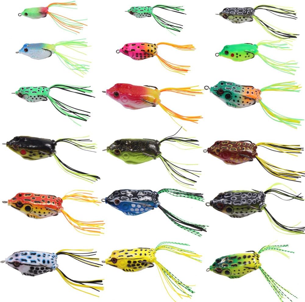
Croch Hollow Body Frog Lure Weedless Topwater Kit (18 PCS)
If you are looking for the best product that provides you with almost everything you need for bass fishing, then you should consider looking at the Croch Hollow Body Frog Lure Weedless Topwater Kit. It is made using a soft and elastic material. The material is very strong and it also contains very sharp hooks.
It also features a double hook design which enables it to provide an effective hook mechanism. This design increases the chances of catching the fish. The hooks are long-lasting and are placed perfectly which enables them to be 100 percent weedless. This enables it ideal for use in lily pads or weed-choked areas without hanging.
Apart from that, it has a realistic and hollow body which enables the frog walking action on water to be smooth and more irresistible. The interior weighting system and the flow-through design prevents it from snagging or sinking. These frogs are also very effective in heavy aquatic or areas with a lot of fallen timber. When using these frog lures, you should be very keen on your fingers. You should also keep them away from children.4
TECKEL Sprinker Topwater Frog
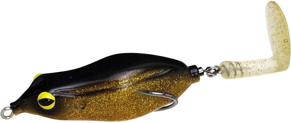
The TECKEL Sprinker Topwater Frog has a slender nose which gives it a mouse like a resemblance. Its shape and the downward tilted nose is designed in a way that prevents it from rolling. It features a rotating boot tail at the back instead of the traditional rubber frog legs. It is placed on a corkscrew keeper and a heavy-duty swivel which enables it to displace water as it moves. It uses both the traditional moving action of hollowed frogs and the agitation of a buzzbait.
It is ideal for close quarters or heavy cover fishing. Its unique design enables it to move smoothly in open water. You have to move it slowly for it to displace water. Its narrow body enables it to move straight and gurgle as it moves around and over cover. You can move it just like a traditional hollow like a frog. The best thing with the body is that it is very soft and collapses well.5
Lunkerhunt Lunker Frog Series 2.5-inch Green Tea Style Fishing Lure
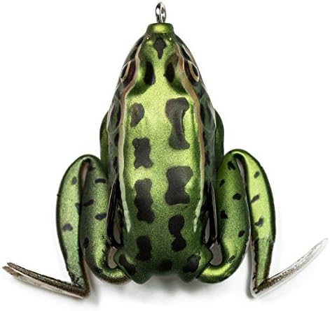
This is another amazing product on the market. With the Lunkerhunt Lunker Frog Series 2.5-Inch Green Tea Style Fishing Lure, you may not have issues catching large bass on your fishing trips. The product is designed in a way that allows it to appear like the real thing. At a first glance, the fishing lure may be mistaken for a live frog.
Even though it is sold at a budget-friendly cost, the product made from top quality and durable materials that will allow for multiple uses in good condition. Also, the body of the Lunkerhunt Lunker Frog Series is supersoft thereby allowing it to be easily swallowed by the fish, thanks to its hollow body design.
It also features a weedless design. The Lunkerhunt Lunker Frog Series 2.5-Inch Green Tea Style Fishing Lure is available in many different colors thereby giving you an opportunity to go for the shade that for you. An amazing feature of the product is that the body of the frog drops a little bit into the water when you are at rest.
Many users find this feature fascinating as it allows the lure to appear like a bullfrog. It is specially designed to be used in freshwater for fishes like pike, bass, and musky. The Lunkerhunt Lunker Frog Series features long fishing legs that are able to extend as you retract, and retrieve, thereby imitating the characteristics of an adult frog. This allows for an increased chance to attract the fish. Another feature is the sticky sharp wide gap hook.6
Spro Bronzeye Frog 65 Bait-Pack of 1
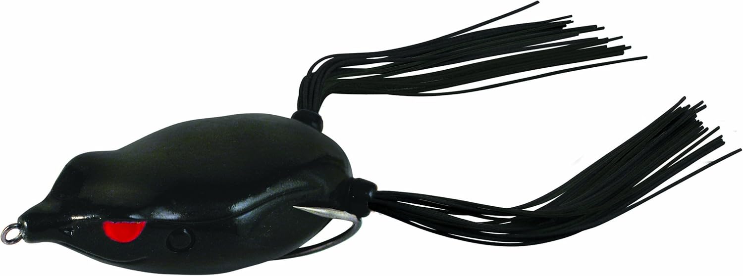
Spro Bronzeye Frog 65 Bait is one of the best product on the market. It has received favorable ratings and reviews from past users which is probably due to the amazing features it brings to the table. Also, it is available in many different bright colors all of which are guaranteed to increase your chances of attracting and catching large fishes. This also allows you to go for the color that works best for you. It is specifically designed for use in both open and heavy cover water.
Furthermore, it is made from top quality material that ensures durability thereby allowing you to enjoy all the benefits the fishing lure has to offer in good condition. The weight, style, and size of the product are ideal for bass fishing. The manufacturer states that the Spro Bronzeye Frog 65 Bait is specially weighted so that most of the weight is centered in the belly of the frog lure. This allows it to appear like a live frog on the water when fishing.
The design of the product also allows you to cast it to a long distance. The hooks are sharp and will properly hold the fish thereby preventing the loss of your catch. However, some users complain that it is more expensive compared to similar products on the market.7
Livetarget Hollow Body Frog
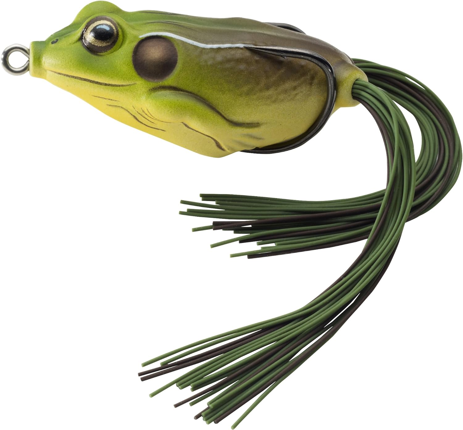
This is another amazing fishing lure on the market. If you are looking to purchase a product that looks like the real thing coupled with high chances of catching large bass for a budget-friendly cost, you should consider looking at this one. The Livetarget Hollow Body Frog is designed with top quality material to provide you with all the benefits you could ever get from frog lures. It is made from a soft plastic.
It is available in many different enticing colors that will increase your chances of a big cat as well as giving you a chance to go for the one that works best for you. Interestingly, the Livetarget Hollow Body Frog won the 2010 ICAST “Best of Show” award. It comes with an amazing soft body design that compresses thereby by making it easy for the fish to swallow for a better grasp. The frog lure is coupled with double ultra sharp hooks that will make it almost impossible for you to lose your catch.
Also, the Livetarget Hollow Body Frog features a weedless design that allows the product to be used over the cover without the need to worry about the lure hanging up. With the product, you can easily cast your hook to long distances thereby increasing your chances of catching big fishes like pike and bass. It features the perfect weight, size, and design thereby making it an ideal addition to your tackle kit.8
Supertrip Topwater Frog Crankbait Tackle Crank Bait Bass Soft Swimbait Lures Crankbaits Baits Hard Bait Fishing Lures (Multicolors)
This is the last product on our list but definitely not the one with the least features. The Supertrip Topwater Frog Crankbait Fishing Lures is another highly rated product on the market. The fishing lure is designed to make your fishing trips amazing as it is focused on helping you catch large fishes like bass and pike.
It is made from a top quality product that will go a long way to ensure durability and longevity of use. It comes in many different bright and attractive colors that are guaranteed to increasing your chances of making a big catch. This feature of the Supertrip Topwater Frog Crankbait Fishing Lures is further complimented by the live frog-like action of the product when dropped on the water.
It is made with a pretty soft plastic material that makes it easy for the fish to swallow your bait. The super soft design of the product also allows it to easily compress by the fish thereby revealing the sharp hooks. In addition, the double hooks will go a long way to ensure that you don’t lose your catch.
You willl find that the quality and shape of the hook still remains intact even after multiple uses. It has a weight of about 12.3g and a length of 5.45cm. The package includes 6pcs baits. Many users like that the product is relatively inexpensive. It makes a perfect addition to your tackle kit.
Conclusion
We hope that the article will help you identify a good frog lure which will help you when fishing. The best thing with the above frog lures is that they have been tested and are very effective. You will realize that they have all the features you would expect from quality frog bait.
This brings us to the end of this informative article. It is also our hope that you have learned a lot about topwater fishing, have you?