2024 Ultimate Guide: Measure Current with an Oscilloscope | Techniques & Tools
Measure Current With Oscilloscope

The Oscilloscope: How to Measure Current
Using a shunt resistor while measuring current with an oscilloscope requires some math to do in your head to interpret the waveform. If you need to record your waveform, this can be confusing. A current probe is a simple way to measure current using an oscilloscope.
Oscilloscopes can display the waveforms of electronic signals and analyse them. The device plots the signal voltage at the moment as a function time. Current probes for oscilloscopes can be used to measure current and voltage. This extends their usefulness beyond the voltage measurement.
If a DC power supply has a current sense resistance (“shunt”) resistor, this is the best method. Good results can be obtained if the probe is operating within its designated range of operation and the voltage drop exceeds the threshold.
Low-level signals require a different kind of differential probe. This requires that the equipment be noise reduced. Use the lowest possible probe attenuation, limit the bandwidth of the oscilloscope or probe to reduce noise in the measurement system.
As current flows through a conductor, an electromagnetic flux field is created around it. The current probes detect this flux field’s strength and convert it into a voltage which can then be measured with an oscilloscope. This allows you to use an oscilloscope to view and analyze current waveforms.
Current probes, when used in conjunction with an oscilloscope’s voltage measuring capabilities, enable you to make a wide range of power measurements. These metrics can include instantaneous power, actual power, apparent power, and phase, depending on the oscilloscope’s waveform math capabilities.

How To Measure Current With An Oscilloscope: A $10 Current Probe
The ability to measure current using an oscilloscope can be useful at times, for example when characterizing an unknown impedance or when designing current limiters. The only snag is, that an oscilloscope measures voltage versus time. So to measure a current with an oscilloscope, some kind of current probe is needed. Such probes are available commercially, but their prices typically start a bit shy of $1000 and extend well into the kilo-buck range, which places them well out of reach for the average hobbyist. There are many other options.
Oscilloscope current probes can enable oscilloscopes to measure current and thereby extend their use beyond just that of measuring voltage.
A scope current probe is useful in many situations, where it is needed to measure current and not voltage. Although this is a good way to measure the current, it has some drawbacks. The best option is to use a scope current probe as this will directly measure the current with less disturbance of the circuit.

Current Probes: Measures current in the field without turning off power
Current probes can be used with oscilloscopes to provide optional measurement functionality. These probes are distinguished by their ability to measure current, even without the need for the circuit to be turned off. With most multimeters, the circuit must be shut off so that the instrument can be placed in series with the circuit in order to measure it.
However, since current probes don’t require the circuit to be disconnected, they’re capable of more accurate measurement than digital multimeters while minimizing effects on the circuit. That said, you may wonder why current probes can measure current simply by being affixed to a wire.
Design Considerations When Measuring Current With A Shunt Resistor
Introducing a sense resistor in series with the load requires careful design consideration. As the resistance value increases, the voltage drop per ampere increases according to Ohm’s Law, thus improving the quality of the current measurement. However, the power dissipation in the resistor increases with the square of the current and the additional voltage drop must be accounted for. In addition, resistors add inductive reactance to the circuit.
And don’t forget that the differential probe input capacitance appears in parallel with the sense resistor, forming an RC filter.
If you were into this, you might also like
Bidirectional Scan Tool
To minimize common mode signals that are transmitted by the measuring system, you should add a sense resistance to your circuit. The common mode rejection performance of differential voltage probes tends to decrease over time, which can reduce the precision of high-frequency current measurements using sense resistors.
How to Use a Current Probe
It’s not particularly difficult to use a current probe. Current probes are used by connecting them to an oscilloscope. It can be very simple to connect current probes with Hioki Memory HiCorders. They have one-touch connectors BNC.
Some models have functionality that makes measurement more efficient, for example automatic zero adjustment and demagnetization (which can be performed by pressing and holding a button).
The AC/DC zero flux current sensor is a current probe that can be used with oscilloscopes. It uses a Hall element for current detection. Combining the CT method with a Hall element allows for both DC and AC current to be measured.
In addition to being able to measure both DC and AC current, this type of current probe provides excellent linearity without being affected by the B-H magnetic characteristics of a magnetic core. It also delivers a broad frequency band with high S/N performance. The absence of excitation noise also means that overall noise is extremely low during measurements.
The Current Sensing Transformers
CST-1030 can sense currents of up to 30 A. RMS. For easy connections to testing equipment, I installed mine with a connector BNC.
It is simple to use the current transformer. Simply feed a wire with the current that needs to be measured through the hole in the transformer, and measure the output of the transformer. This transformer can be used at 50-60 Hz power line frequency, but it has a surprising wideband.
Bandwidth
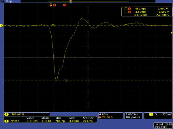
The CST-1030, which is not a Hall effect sensor but a transformer, cannot measure DC current. However, as the measurement below shows, it does come quite close.
The bandwidth of the CST-1030 is wider than the measurement capability of the APx525, so to find the -3 dB points, I used a function generator and an HP 34401A multimeter. At a test current of 250 mA, the CST-1030 showed a bandwidth of 3.2 Hz – 330 kHz, which is certainly plenty for measurements within the audio band.
Increasing the Sensitivity
If you were a fan of this, you might also be into
Hantek Oscilloscope Review
With five turns on the primary (as shown above), the sensitivity of the current transformer is increased fivefold, thus, the transformer delivers 0.5 V/A. As shown in the measurement below, this increases the bandwidth of the transformer at lower frequencies when measuring lower currents.

How To Measure Inrush Current
Technicians can use a hard-jawed clamp meter or a flexible current probe to measure inrush current. Meters with an inrush button can measure the inrush current. Here are the steps to measure it.
Make Use of a Shunt Resistor
This understanding reveals that the voltage across a resistor corresponds to its current. It is therefore the easiest way to measure current. Ohm’s law might be summed up as keeps: V = IR, Where V indicates the voltage across the resistor, ‘I’ is the current through the resistor, and R signifies the resistor’s opposition, all in ohms.
If you appreciated this, you might also enjoy
Best Oscilloscopes
Figure 1: Shunt resistor circuit
The power accomplishes no beneficial work since the resistor turns the current into a voltage for measurement. One meter ohm would produce a small but detectable voltage drop across the resistor, which allows for meaningful voltage balance.
However, differential probing low-level signals requires that noise be removed from the measurement apparatus.
Limit the level of estimation framework noise by using the smallest possible test weakness and limiting recurrence on your oscilloscope or test. Remember that the test’s capacitance and opposition will, in any case, be in correspondence with the detecting resistor. While this is intended to reduce the influence of the system under test, you should be aware of it.
Assuming you should remember a detecting resistor for the circuit, place it as near unbiased as possible to lessen the normal mode flags that the estimation arrangement should dismiss. High-performance current probes can’t measure differential voltage at high frequencies. This decreases the common mode rejection of these measurements, which lowers reliability when using sense resistors.
Figure 2: Measurement of Differential Voltage

What is the best way to measure current as a voltage drop across a shunt resistor?
This is the most practical approach.
However, if you use a differential probe to measure low-level signals, it is important that noise be reduced in your measurement system.

The Theory
A shunt-based current detector is a simple idea.
Current sensor for shunting
To measure the voltage drop across the resistor and work out the current through it (and the load), we connect a resistor to the load. It’s very simple and straightforward, but there are two issues:
A differential amplifier is used to amplify the voltage across Rsense and to output an amplified difference in voltage relative to ground. The amplification solves these problems by allowing us to use very low Rsense, have very little voltage drop and still get a high sense voltage. Also, shifting the sense voltage relative to ground simplifies measuring.

Component Choices
This is a very common application, so although you can use a generic differential amplifier (or instrumentation amplifier), there are many products designed and optimised specifically for this use, with most of the necessary external components integrated into the chip, usually sold as acurrent-shunt monitors/amplifiersa, and itas a good idea to use them. I chose the Texas Instruments INA213 current shunt monitor, because itas cheap (US$0.587 each from JLC), has a very low offset voltage (Voff) of A+-35 AuV, which allows me to minimise the burden voltage by using a very small shunt resistor. You can also get high-precision integrated ADCs with digital output (either I2C, or SPI), but as we’re reading with an oscilloscope we’ll stick with standard voltage output devices.
Voff can be thought of as a voltage error on the input. To maintain an equal signal-to noise ratio (SNR), the Voff is greater than the Rsense. Therefore, Voff is one of the most important parameters for a differential amplifier.
The INA21x series comes in many different gain options from 50 to 1000. Generally, higher gains allow the use of a smaller resistance and hence lower burden voltage, but increases noise, and decreases bandwidth, since amplifier bandwidth is usually inversely proportional to gain a see Gain-bandwidth product%20and%20vice%20versa.). That is the case here as well. My 50x gain model has an advertised bandwidth at 80 kHz, while the 1000x model has 4 kHz. I chose 50x gain because bandwidth is more important to me than burden voltage, which is already low enough at 50x, which would give me a 1V output from a 20 mV burden voltage. My circuits donat usually care about anything as small as 20 mV.
The INA21x series is also capable of being powered from anything between 2.7V and 26V. This covers the majority of my supply voltages. That means I can make the setup simpler by trading flexibility for convenience and just power the amplifier from my power supply.